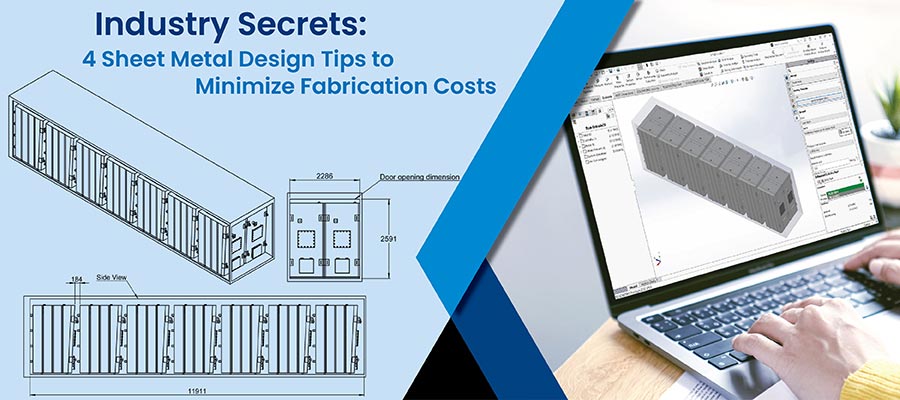
Sheet metal fabrication costs are driven by design complexity, material choice, and precision requirements. Utilizing CAD for detailed sheet metal modeling significantly reduces rework, enhances quality, and speeds up production, offering substantial cost savings and productivity improvements.
Table of Contents
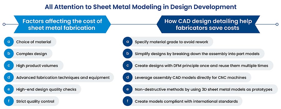
Factors like design complexity, type, and grade of sheet metal, tooling equipment, and process contribute to the cost of sheet metal fabrication. For instance, products like kiosks, doors, and windows have a lower degree of design complexity and need low precision, whereas HVAC equipment or electrical enclosure panels need high precision.
The final product is another important factor influencing metal fabrication costs. Fabricators thus rely on comprehensive sheet metal modeling to stay competitive. Creating detailed sheet metal part models enables driving precision in design and open room scalability and flexibility. It ensures clear design intent communication with stakeholders to deliver quality products.
Design detailing in sheet metal fabrication is not just about shaping and cutting metal; it involves a holistic approach to designing parts in CAD in a way that maximizes functionality while minimizing waste and simplifying assembly. The right design choices can streamline the manufacturing process, reduce material usage, cut time in CAD modeling, and decrease machine time-each contributing to a lower cost of fabrication.
Additionally, CAD technology has significantly reduced design-to-manufacturing time and enhanced sheet metal part modeling accuracy for manufacturers.
Following the best practices in sheet metal drawings and detailing drives:
This is merely a glimpse of several other benefits of using 3D CAD modeling for sheet metal product design and development.
Do not miss out on the 70% faster design-to-manufacturing cycles
Unlock the benefits now »Feature based parametric 3D models and 2D drawings share parent-child relationships as drawings are generated from models. This bi-directional parametric link between models and drawings allows the design engineer to evaluate changes in 2D sheet metal shop drawings and 3D models simultaneously.
Complex sheet metal components use multiple features to convey design intent and show part functionality. Figure 1 shows a typical sheet metal component model with design features.
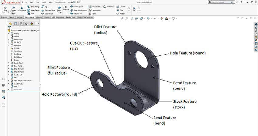 Figure 1: Sheet metal features and their categories
If you are working on a single component, you can apply Design for Manufacturing (DFM) concepts and it directly conforms to standard manufacturing processes. Adherence to DFM guidelines for 3D models helps optimize manufacturing operations, such as nesting, bending, holes, and punching.
Benefits of using FBPM:
Hitech CADD Services’ design engineers carried out reverse engineering of a recycling plant in Europe. They recorded physical dimensions and developed a 3D plant assembly model in SolidWorks. Deliverables also included GA drawings, 2D part drawings, and parametric 3D models. It assisted design engineers in making informed decisions for plant restructuring and improving efficiency.
A top-down approach is used to model a product with multi-component sheet metal parts. This design approach allows you to create a geometric frame with space constraints assigned to all parts and sub-assemblies. It builds the master model in such a way that it can be used for CTO and ETO feature customization for products such as doors and windows, metal, and wooden furniture, etc.
CAD tools like SolidWorks, Inventor, and Creo allow a top-down approach for very large and complex assemblies. These include heavy-duty bulk material handling plants having 10,000+ components in a single master model. These CAD platforms are also fit to handle small assemblies of sheet metal doorframe having not more than 20 to 30 parts with dexterity.
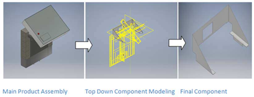 Figure 2: Top-down design approach for a small sheet metal assembly
Advantages of the top-down design approach:
Hitech CADD Services engineers developed 2D manufacturing drawings and 3D models of a recycling industry plant and equipment manufacturer. Project engineers adopted a top-down approach to converting STEP files and solid models of the plant assembly for walkways and hoppers. A systematic approach to building the model met all design guidelines, avoided reworks, and saved time in redesigning.
Are you looking for a partner to outsource sheet metal design drawings?
Contact us »Design for Manufacturing (DFM) and Design for Manufacturing and Assembly (DFMA) allow design engineers to capture requirements as per shop floor capabilities. Following these guidelines nullifies most of the design errors that arise from nonconformity with the standard shop floor practices.
DFM guidelines help design engineers bridge the gap between the real world and the ideal world while creating features like holes, slots, bends, end reliefs, etc. Figures 3 and 4 are examples of hole creation and bend radius creation, respectively, in sheet metal.
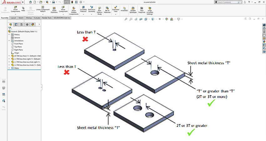 Figure 3: Punching holes in sheet metal plates according to DFM rules
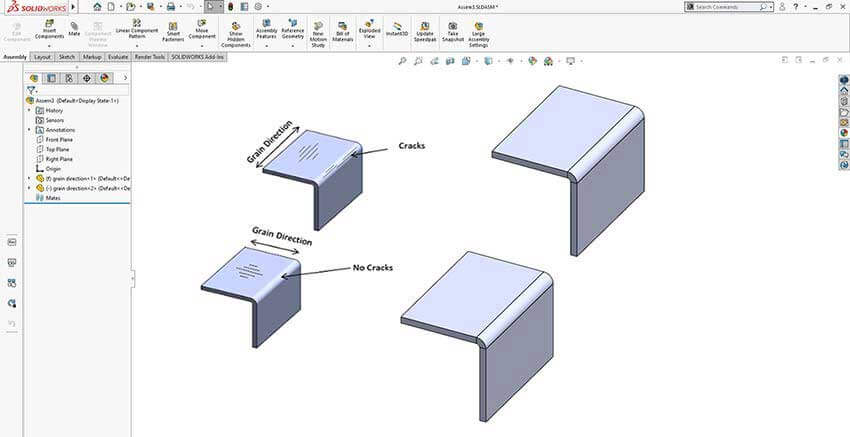 Figure 4: Bending failure in sheet metal plate without considering grain direction
With DFMA guidelines, engineers are empowered to optimize designs by controlling the number of components and steps involved in manufacturing. With fewer components, fabricators can save costs and speed up the production process due to the ease of assembly and fabrication.
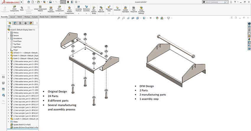 Figure 5: Considering a number of sheet metal parts in the assembly as per DFM guidelines
Advantages of DFM and DFMA
Hitech CADD Services’ sheet metal design team migrated legacy design data from AutoCAD® to SolidWorks using APIs for a Stairlift manufacturer. These 3D models and fabrication drawings enabled the standardization of all files in SolidWorks as per DFM guidelines and international design standards to eliminate rework.
Advancement in tools like SolidWorks ensures incorporation of a high level of manufacturing and quality information in models. They have provisions to annotate models with product manufacturing information and create a single source of truth for all design and manufacturing stakeholders. By saving all information in one place, this concept has significant potential to meet the needs of Industry 4.0.
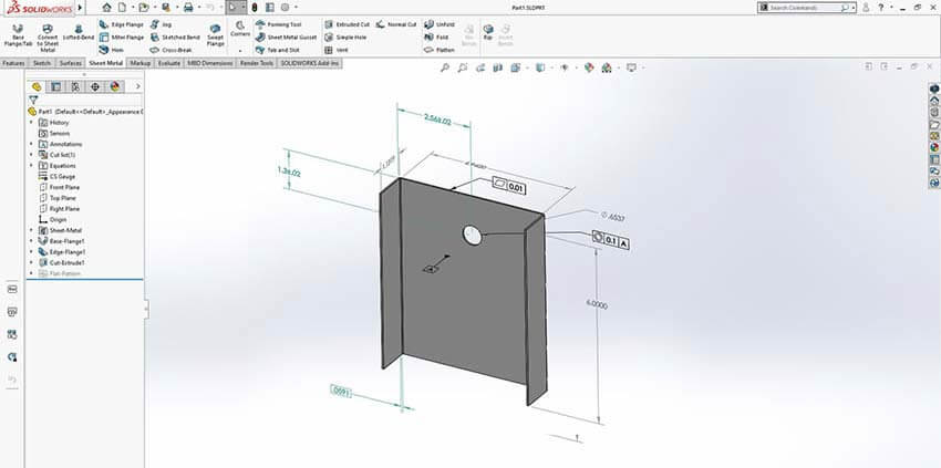 Figure 6: MBD representation of a sheet metal plate
A complete set of product information for manufacturing and suppliers, such as quality measurement, tolerances, other footnotes, etc., is communicated using a comprehensive 3D model. This is called the Model-Based Definition (MBD) approach.
MBD creates a single, reliable CAD file for the entire value chain to improve collaboration, save time, and prevent errors. If used efficiently along with DFM, DFMA, FBPM, and the top-down approach, MBD can prove to be significantly advantageous to manufacturers.
Advantages of MBD
An electroform systems manufacturer sped up the design development of high-precision metal parts and cut the time to almost half using SolidWorks MBD. A single file for all inter-team communication sped up publishing PMI in 10 minutes instead of one day and eliminated the need for paper drawings. (Source: SOLIDWORKS)
Cost-efficient sheet metal fabrication is grounded in the adoption of robust design practices. Embracing best practices in sheet metal part modeling significantly optimizes the fabrication process. They facilitate a reduction in material waste and machining time and enhance the overall quality and precision of the final products. With up to a 90% reduction in rework and redesign, substantial cost savings, and accelerated design-to-manufacturing cycles, the benefits of implementing these methodologies are profound and far-reaching.
For any fabricator aiming to thrive in the dynamic market of sheet metal fabrication, integrating these practices into their workflow is essential. By doing so, they ensure that they not only keep pace with industry standards, but also leverage technological advancements to deliver superior quality products efficiently and cost-effectively.
Sandip Shah is a mechanical design engineer with a track record of 22+ years of delivering winning solutions across new product design, value engineering, and digital manufacturing/IOT projects. He has successfully steered business units of 2 million through his excellence in project management, global account management and lean planning in CAD/CAM and CAE tools.
Nimesh Soni with 15+ years of managerial role in industrial design industry, manages furniture design vertical at HitechCADD Services. For the past 9 years at Hitech, he has delivered winning solutions for a range of turnkey projects with his expertise in SAP/PLM and CAD tools. His current research work towards a doctoral degree in IOT gives him an advantage in identifying automation opportunities across design-to-manufacturing cycle.
You may also like
The Role of Millwork Detailing in Modern Architecture