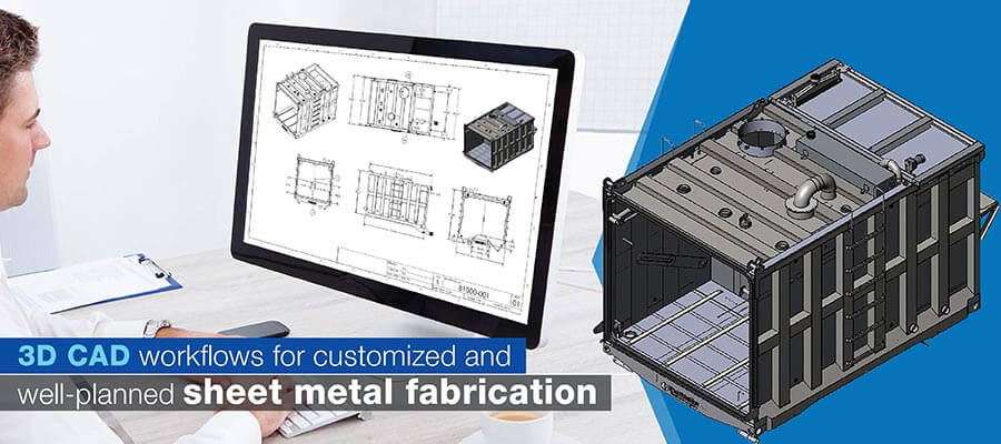
Traditional sheet metal fabrication design methodologies tend to be slow and do not provide high accuracy when creating products. The use of 3D CAD modeling for sheet metal fabrication offers faster engineering lead times, better visualizations, enables direct manufacturing of parts and improves collaboration between design and production departments.
Table of Contents
Sheet metal product design needs to be planned with the customer in mind. When a customer orders a door frame, enclosure, duct or panel they want to see how the finished product will look from all sides before purchasing. Traditional 2D drawings typically do not communicate the designer’s intent to the fabricator well enough and also do not allow for fast design changes which results in the need for rework, increased costs and project delays.
The use of sheet metal design has changed the way that engineers, fabricators, product designers and manufacturers work together. A complete 3D modeling for metal fabrication platform will ensure that there is a smooth transition of information from the designer to the manufacturer improving accuracy, productivity and communication.
Here we examine the importance of 3D CAD modeling to modern sheet metal product fabrication industry, specifically, the problems it solves, the characteristics of the technology and its many benefits.
The 3D CAD modeling process creates a three-dimensional model of a part made from sheet metal using a variety of 3D CAD software programs. A major advantage of designing with 3D CAD is that you can develop a realistic 3D model of your part and then assess how they will be fabricated. Therefore, you can catch problems that could occur prior to fabrication.
Sheet metal fabrication began as a completely manual process of cutting and shaping metal. As such, traditional sheet metal fabrication techniques were both labor intensive and prone to errors. The introduction of CAD drafting for sheet metal fabrication provided a new method of fabrication.
Industry standard tools like AutoCAD, SolidWorks, and Autodesk Inventor have become essential in modern sheet metal design. These offer specialized features for bend allowances, flat pattern development and considerations for material thickness.
In addition to being faster and less labor intensive than traditional fabrication techniques, the accuracy achieved through 3D CAD is also significantly better.
In fact, the entire fabrication process can now be fully planned and visualized using 3D CAD. This means fewer errors in the finished product and reduced production times.
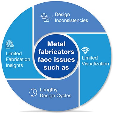
While 2D drawings have been successful for many years, there have been several challenges associated with them. Some of the primary challenges include:
Moving away from 2D drawings and into 3D CAD models can resolve all of the above mentioned challenges and provide many additional benefits to the sheet metal product fabrication process.
3D CAD modeling has changed the way we think about designing, engineering and manufacturing sheet metal products. For product designers, engineers and fabricators, here’s what 3D CAD can do to enhance the process of sheet metal fabrication beyond traditional 2D drawings:
Establish seamless workflows across stakeholders.
Hire a 3D CAD expert »The advantages that 3D CAD modeling provides to sheet metal fabricators and designers creating building products (HVAC systems, roof panels, wall cladding) include:
Many modern 3D CAD systems contain numerous new features that assist with all aspects of fabrication, from conceptualization to completion and provide numerous ways to increase the speed of fabrication and decrease costs.
3D CAD modeling incorporates Design for Manufacturability (DFM) guidelines to create products that are both functional and inexpensive to manufacture. As a result, fewer design revisions will be required thereby reducing both the time and cost associated with creating and manufacturing product prototypes.
CAD sheet metal design services utilizing tools such as SolidWorks & Inventor provide users with in built DFM features for making automatic design for manufacturing recommendations.
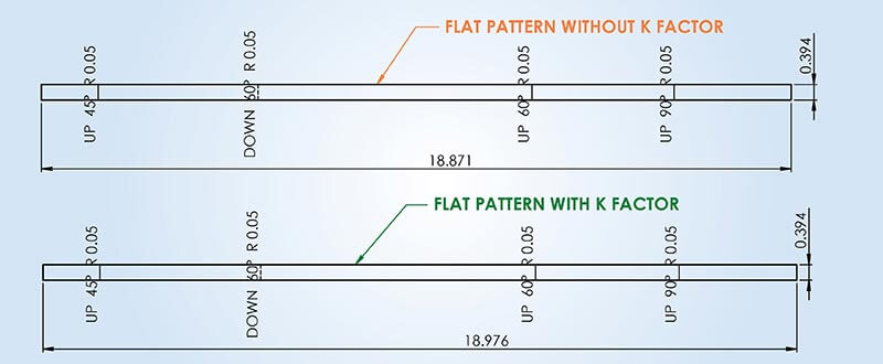
For example, when designers do sheet metal bending and forming for components, there are a few things that need to be considered, specifically accurate K factors that will minimize springback of the bends. The designer must calculate the correct value of the K factor for each type of bend on each piece. Bend allowance calculation values for different types of metals vary. Modern CAD software provides K values for various types of metals, including steel, copper, brass and aluminum, among others.
The designers can create accurate flat patterns using a 3D model, which assist in generating DXFs for cutting, as well as estimating the cost of fabrication. Most 3D CAD software for sheet metal includes the ability to generate flat patterns from 3D models and this allows sheet metal fabricators to be able to cut and fold their materials with greater accuracy. This capability for flat pattern generation decrease material waste and the possibility of errors occurring during the fabrication process.
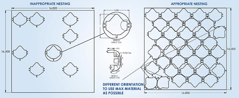
Nesting optimization is defined as the arrangement of flat patterns in a manner that maximizes the amount of material used. Using 3D CAD allows the fabricator to automatically do nesting, thereby minimizing scrap and conserving the cost of raw materials.
Nesting optimizes the usage of raw material in manufacturing sheet metal components and also provides savings on the scrap. It follows three basic rules:
The use of 3D CAD modeling to assist in the design process integrates many of the design for manufacturing and assembly (DFMA) principles into the process. The integration of DFMA into the design process help to lower the costs associated with assembling products and improve quality of the products since parts fit properly when assembled at the end of production.
Using DFMA as a guideline designers are able to limit the number of components in the 3D assembly model. Many modern CAD systems include a DFMA module to check for clearances quickly and offer suggestions on how to combine multiple parts or limit the total number of components that need to be combined to assemble the parts.
Overcome Sheet Metal Fabrication Challenges with Detailed Shop Drawings
Struggling with project delays and costly errors in sheet metal fabrication?
Discover how to:
Start optimizing your sheet metal fabrication process!
Download your copy Today!Detailed sheet metal 2D drawings can be produced from 3D CAD models that have very high accuracy. The models contain all necessary technical information with geometric dimensions and notes to limit potential manufacturing errors.
Since the 2D drawings are developed from the parent 3D models, any changes made to the parent models will reflect those in the corresponding 2D drawings. Using this process enhances communication among various departments such as the shop floor, purchasing and quality. 3D CAD models of sheet metal parts have accurate BOMs that allow users to determine the amount of raw materials needed to keep optimal inventory levels.
Make every sheet count with optimized nesting flat patterns and accurate BOMs.
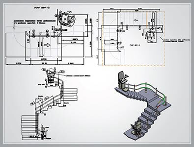
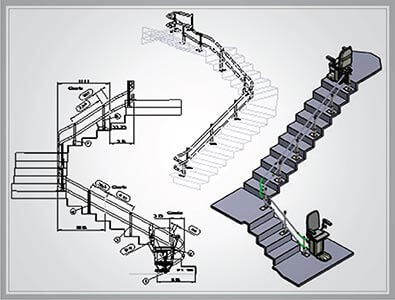
Get in touch with us »3D modeling & fabrication drawing for stair lifts manufacturer
A European company was looking for a reliable way to create 3D models of stairlifts and create fabrication drawings. Due to design changes happening frequently, not having enough internal resources to generate CAD designs and a lack of documented standardization processes resulted in delayed communication between the engineering teams and the production teams.
Hitech CADD Services generated detailed 3D models and fabrication drawings using SolidWorks for multiple stairlifts. The teams created standardized parts, assemblies and documentation which allowed rapidly integrating design changes into models, validate manufacturability and verify that the documents met the company’s production standards so they could be utilized seamlessly by the production teams downstream.
The end results were:
 Stairlift 3D CAD Model
 Stairlift Manufacturing Drawings
To produce parts efficiently and minimize cost, it is important for both fabricators and engineers working with sheet metal to follow Design For Manufacturability (DFM) guidelines. 3D CAD allows designers to incorporate DFM guidelines into their designs from the onset, thus creating more manufacturable designs. Studies show that companies utilizing 3D CAD are able to reduce production times up to 30%, as well as cut material costs by 20%.
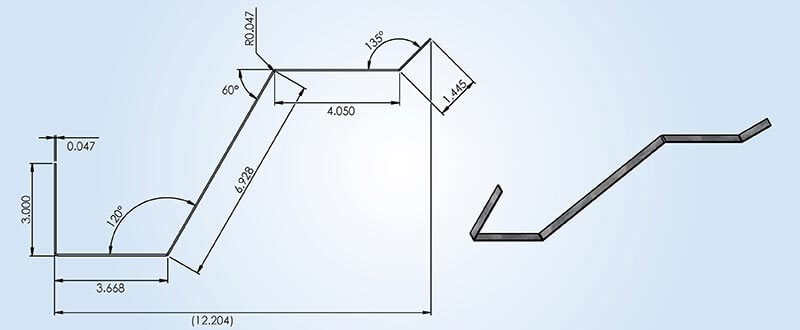
A flat pattern is a two dimensional depiction of a three dimensional sheet metal component, showing the exact layout for cutting and folding. 3D CAD facilitates the generation of flat patterns by automatically producing them from a 3D model. This guarantees that the generated flat pattern will match the folded item exactly, resulting in fewer opportunities for error when cutting or bending during fabrication.
In sheet metal fabrication, achieving maximum use of material is key to reducing waste and decreasing costs. The nesting feature in 3D CAD enables the user to configure multiple flat patterns on a single piece of sheet metal in an optimal manner. As a result of this optimized configuration, there is less scrap material produced. Therefore, the production process becomes more cost efficient and environmentally friendly.
By applying DFMA (Design For Manufacturing and Assembly) into 3D CAD design engineers may create designs that have been optimized for manufacturing and assembly by considering manufacturing and assembly aspects from the start of the product development process. This will ultimately lead to faster production times and lower cost as well as fewer errors during the assembly phase.
In order for sheet metal fabricators to properly fabricate a product, it is important that they receive an accurate 2D technical drawing of the product so that they can fabricate the product to correct specifications. The 3D CAD software will generate the 2D technical drawings as well as provide a detailed bill of material (BOM). A detailed BOM includes a list of all necessary components to ensure a smooth fabrication process while eliminating the need for manual measurements or guess work.
In addition to seamless communication between the designers of building products and their customers, modern CAD tools offer several other options for improving visualization and productivity of designers to create an effective link between sales and manufacturing.
The two most important elements to convince customers are good design visualization and the ability to customize. With 3D CAD, customers can view the building product in 360 degrees using rendering and walkthroughs of customized designs created by them.
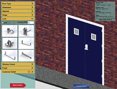
3D visual configurator creates designs based on defined rules and specifications. A customer can select a door frame from the web portal and enter in their specific needs. Once the design is complete, customers will be able to view the 360 degree design, including rendering and walkthrough, of the custom designed building product. Customers will also receive a quote and lead time for delivery right away even when no sales staff are available.
The capabilities of advanced 3D CAD modeling platforms enable direct manufacturing capabilities through CNC sheet metal fabrication by sending DXFs to machines used for cutting metal sheets, thus eliminating human involvement in machining and minimizing errors.
Additionally, MBD features in 3D CAD modeling improve both the collaboration and the value chain from sales to manufacturing. Designers are able to embed all product information into a single 3D CAD model which becomes the single source of truth for the entire value chain.
Design Automation for Hollow Metal Doors & Frames Manufacturer
A U.S. company that produces hollow metal doors and frames had problems due to poor sharing of information between departments, inadequately defined methods for dealing with custom orders and duplication of work by the engineers. These problems resulted in lengthy delivery schedules, numerous mistakes and the inability to quickly respond to customer’s specific requests for new designs.
Hitech CADD Services developed a configurator using DriveWorks which was integrated into SolidWorks, to create an automated method for creating 3D models, manufacturing drawings and quotes. The tool allowed the sales staff to enter in their own unique requirements as input and have instant creation of the required documentation that would be used to produce the product with very little or no input from the engineers.
The end result was:
 3D Door Configuration
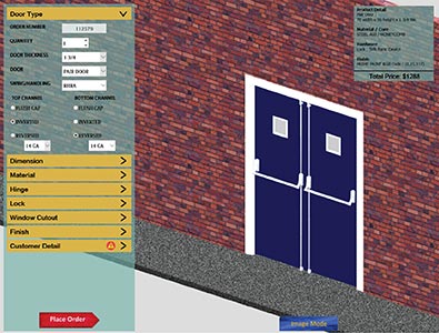 3D Door Component Configuration
Automation and robots are increasingly being used to address the most intricate and difficult to manufacture parts of products in order to minimize the potential for error and to maximize the manufacturer’s productivity.
There has been development in additive manufacturing, allowing for the creation of geometric forms that would be virtually impossible to manufacture through traditional sheet metal fabrication processes. There is also a growing focus on environmentally friendly practices such as using recycled materials in manufacturing processes.
This will increase the ability of manufacturers to innovate and produce their products more efficiently than ever before. As such, it is the manufacturers who develop new technologies and incorporate them into their manufacturing processes that will be at the forefront of the industry in the coming years.
The 3D CAD process offers greater visual understanding than 2D drawings. It is also fully compatible with CAM (Computer Aided Manufacturing) systems that allow for automatic cutting, folding and assembly operations. With 3D CAD process, assessments and stress tests can be performed prior to the start of fabrication, which help identify potential problems.
The 3D CAD method can be used to minimize material waste mainly by optimized nesting and correct, exact flat pattern generation. Nesting algorithm is designed to organize flat patterns created from 2D drawings on a roll of sheet metal with the most possible use of it. Also, flat patterns eliminate errors in cutting and bending.
Using 3D CAD offers a single, visual representation of the model, allowing all stakeholders to work together. Designers, engineers and fabricators can make changes in “real time” and all stakeholders will see the changes as they occur. They will also have fewer misunderstandings and less opportunity to produce parts incorrectly.
DFMA or Design for Manufacturing & Assembly provides assurance that your products will be manufactured efficiently & easily assembled. By simplifying parts & improving assembly time/costs of the end product, DFMA improves the efficiency of the production process and reduction of waste.
The transition from 2D drawings to 3D CAD models in modern manufacturing is a requirement in order to be successful. 2D to 3D CAD conversion improve precision, efficiency and helps minimize material usage and provide opportunities for engineers, fabricators and manufacturers to improve their production processes as they evolve. 3D CAD will have an increased role in shaping the future of sheet metal fabricated products.
The growing need for customized products and quicker delivery times enable sheet metal fabricators to use 3D CAD modeling in reducing inefficient design and material waste. It also allows for improved collaboration among individuals, improves accuracy in shop drawings and reduces repetitive work that can slow down production, improving overall productivity and enabling manufacturers to develop new products and services that are centered around the customer needs.
Amit Panchal Engineering Design Manager at HitechCADD Services, specializes in delivering technically sustainable solutions to ensure quality sheet metal fabrication of building products. He explores CAD design development techniques to meet international quality standards across commercial, industrial and residential verticals of building products manufacturing.
You may also like
Point Cloud to Revit: The Backbone of Scan to BIM Projects
The Role of Millwork Detailing in Modern Architecture