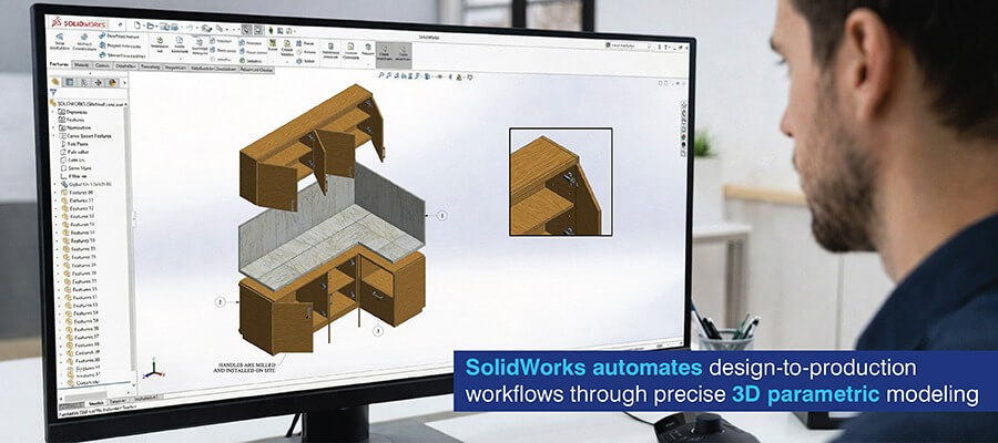
SolidWorks 3D modeling has transformed the way furniture is manufactured by providing an integrated digital workflow that enables designers to create custom furniture designs using parameters, validate assemblies before they are manufactured and integrate directly into the CNC machine.
Table of Contents
Furniture manufacturers who use conventional 2D drafting often struggle with dimensional errors in their products, miscommunications in manufacturing and long delays in updating documentation. A fragmented workflow creates bottlenecks for design validation and complicates CNC programming.
SolidWorks 3D modeling provides a unified digital environment that allows furniture components to be created one time and used throughout the design, documentation and manufacturing processes.
This unified digital process enhances dimensional accuracy, speeds up design iterations and increases communication through the production process. As such, it is ideal for both custom and modular furniture manufacturers looking to increase efficiency in the manufacturing process.
SolidWorks 3D modeling for furniture design gives you one 3D model that is the single source of truth for all your downstream processes.
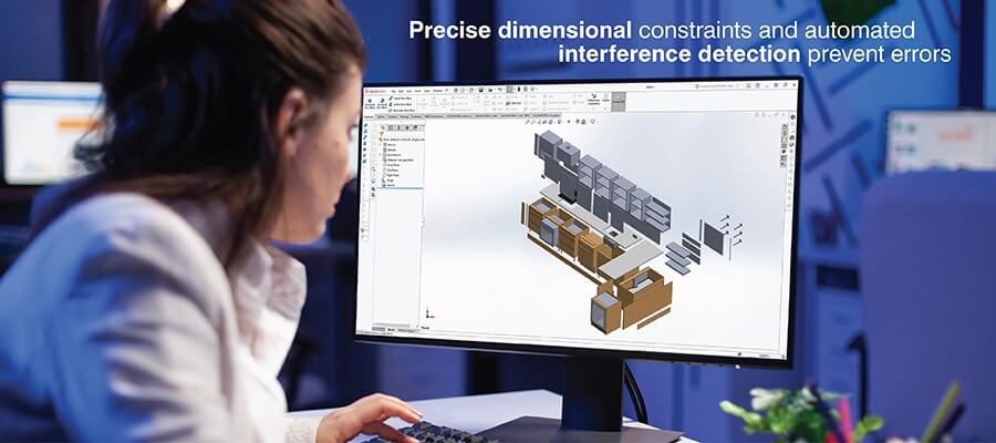
SolidWorks 3D modeling utilizes precisely created volumetric representations of furniture parts with specific dimensioned data, defined edge treatments and joinery characteristics.
For example, in a mortise-and-tenon joint SolidWorks models can represent the exact dimensions of both the tenon and the mortise including positional tolerance to ensure that each component has the correct size, shape, and location.
Similarly, the relationship between components in a dovetail joint are maintained by SolidWorks throughout the process of designing the joint. This helps maintain the spacing, angle and depth of the pin and tail boards.
Parametric furniture design allows the designer to create automatic relationships between features of a part. Thus when one feature is changed other related features also change. For example if you increase the width of your cabinet the system it will automatically adjust the position of the shelves, dividers, etc., based on pre-defined rules.
| Accuracy aspect | Traditional 2D workflow | SolidWorks 3D modeling |
|---|---|---|
| Joinery definition | Dimensioned annotations requiring interpretation | Precise volumetric geometry with explicit tolerances |
| Design changes | Manual recalculation across multiple drawings | Automatic propagation through parametric relationships |
| Production interpretation | Subject to dimensional ambiguity | Unambiguous solid geometry for direct CNC extraction |
| First-time-right confidence | Lower due to interpretation errors | Higher through validated digital models |
The manufacturing team creates tool paths directly from solid geometry instead of having to interpret dimensioned drawings. Therefore, accuracy is preserved during the transition from design to production.
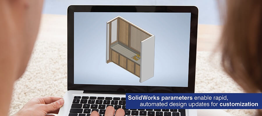
Designers create parametric systems based on the dimensions of products so that when specifications are changed, the product can be updated.
When designing furniture in SolidWorks, designers use parameter values to define the geometric shape of furniture components.
For example, consider a desk model defined by three parameters – “OverallLength=1500mm”, “DepthFromFront=750mm”, and “WorksurfaceHeight=720mm”. When the value of “OverallLength” is changed to 1800mm, then the desk legs will also move, the length of the stretcher will change and the placement of the drawers will also update.
The relationships between the parameters are defined using equations. For example, the equation “DrawerWidth = (OverallLength – 60mm)/3” ensures that the space between each drawer is always equal. Shelf pins may be positioned using similar expressions such as “25mm from the left edge and repeated at 32mm vertical intervals” to ensure that the same pattern of drilling holes exists regardless of how high the cabinets are.
Similarly, hinge positioning maintains the distance between the hinges and the corner of the door regardless of the new size of the door.
Parametric design control allows for an efficiency in the creation of custom furniture variants via 3D modeling:
Scale furniture production with SolidWorks CAD modeling.
Talk to our expert »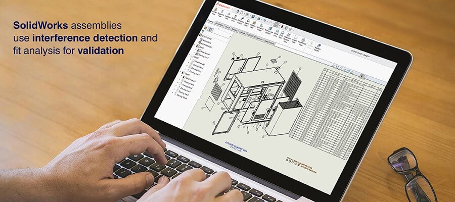
SolidWorks assembly modeling provide digital validation environments that check for errors prior to producing physical products. Furniture system assemblies validate functional relationships and construction rules digitally.
SolidWorks assemblies for furniture constitute entire functionally unitary component set where each element is positioned as it will be in the final product relative to other elements. An example is a cabinet assembly, which can include carcass, doors, drawer boxes, slides, hinges and feet.
For example consider a drawer assembly: The drawer front will constrain “flush” to the face frame by 2 mm. The drawer slide will constrain “parallel” to the cabinet side at 150 mm in height and will have “coincident” constraints to the mounting hole.
The constraints define the geometric dependency of how things cannot be placed in an impossible configuration. Thus the assembly technician may see the relationships intended to be mated. Like which edges of a part meet, what surface of one part meets what surface of another and what clearance exists for the purpose of serving as interactive assembly instructions.
Design validation in furniture manufacturing is done by means of systematic checking of geometric relations. Detection of collisions (interference) reveals the potential conflicts for example, drawer box interfering with an internal divider, or screw of hinges going through the visible surface.
Extension slides are animated through the full travel range and they confirm that the space of 12 mm is always kept throughout the operation.
Virtual validation of furniture designs via furniture prototyping with SolidWorks is the basis of testing different versions of configurations, evaluation of ergonomics and verification of assembly sequences before manufacturing the actual products. This leads to a reduction in the amount of expensive prototypes needed to be built physically.
3D modeling with DFM support for a retail store furniture manufacturer
A retail store furniture manufacturer in Europe was facing manufacturing inefficiency based upon legacy 2D drawings, repeated design efforts and poor quality of drawings causing assembly complications. The client required improvements in manufacturability, reduced materials waste and shorter design cycles.
Hitech CADD Services converted the clients’ 2D furniture designs to SolidWorks 3D models using DFM strategies and automated the clients’ design process through DriveWorks. This established a standardization of the design process reducing errors, improving visualization and streamlining the design-to-production process.
The end results were:
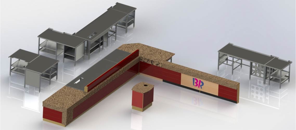 Furniture 3D Modeling for Retail Stores
Creating 3D CAD models in SolidWorks enables the creation of CNC-compatible furniture models by maintaining geometric data in a format directly interpreted by CNC programming software. Machining information like hole locations, pocket depths, edge profiles is stored as geometric objects within solid models.
Key capabilities include:
Design and manufacturing are coordinated using digital furniture manufacturing solutions based upon a common set of 3D models. Using PDM systems that allow both the design and manufacturing teams to access the same SolidWorks file creates two-way communication.
In this environment, designers are able to incorporate manufacturability feedback into their designs and manufacturing is able to clearly see what was intended by the designer.
The use of collaborative design in SolidWorks also allows for multiple designers to work on the same project at the same time.
For example, one designer may develop the cabinet structure and another designer may develop the drawer assemblies as part of the same assembly. The check-in and check-out protocol eliminates conflicting edits from multiple designers working on the same assembly.
| Collaboration aspect | Implementation | Benefit |
|---|---|---|
| Shared 3D models | PDM-managed access | Unified design reference |
| Automatic BOMs | Extracted from assemblies | Current material and hardware lists |
| Digital annotations | Model-based feedback | Faster issue resolution |
| Revision management | Documented change tracking | Prevents outdated manufacturing |
Some key areas where the furniture manufacturing efficiency improves due to improved collaboration include:
SolidWorks 3D CAD modeling benefits offer long-term scalable digital infrastructure, which extends past immediate productivity improvements. The move toward the integration of 3D modeling for custom furniture from a collection of isolated 2D workflows provide long term and sustainable advantages in accuracy, customization and production dependability.
As CNC driven furniture production evolves, the parametric foundation of SolidWorks 3D modeling is essential for providing a base for the implementation of configurators and adaptive manufacturing processes. Companies that develop strong 3D practices are positioned to take advantage of automation technologies yet maintain the ability to create both custom and modular furniture products.
Get SolidWorks modeling support for cabinet manufacturers.
Connect us »
Amit Panchal Engineering Design Manager at HitechCADD Services, specializes in delivering technically sustainable solutions to ensure quality sheet metal fabrication of building products. He explores CAD design development techniques to meet international quality standards across commercial, industrial and residential verticals of building products manufacturing.
You may also like
Point Cloud to Revit: The Backbone of Scan to BIM Projects
 Mar 17th, 2026
The Role of Millwork Detailing in Modern Architecture
Feb 11th, 2026