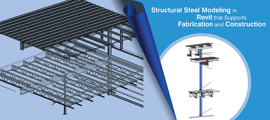
Accurate structural steel modeling ensures correct on-site assembly and smooth construction. BIM coordination with automated conflict detection gives designers, contractors, and consultants greater clarity. These 3D models integrate data and enable parametric detailing, reducing rework and improving quantity takeoffs.
Table of Contents
Structural designers, engineers, specialty contractors, fabricators and consultants that deal with modern architecture require structural details and geometries that are highly complex. They need to incorporate steel grades with high steel strength and intricate connections for sustainable building projects.
Structural steel modeling done correctly ensures precise load paths and seismic energy distribution for structural stability and geometric accuracy in construction projects. When structural teams work with 2D CAD workflows, it often leads to information silos, lack of parametric intelligence, hard clashes, as well as material waste.
BIM based workflows provide streamlined information exchange through IFC formats to all stakeholders. Structural engineers can leverage these and use analytics links to verify designs. With BIM, contractors can leverage steel structural 3D models and improve erection sequences, and steel fabricators can use LOD 400 models for material tracking.
Research shows nearly 46% of the steel in steel-framed structures is actually not required for strength. This extra usage happens because steel sections are over-modeled, using more material than what is actually required.
Source: sciencedirect.comThis article discusses the benefits of structural steel modeling for fabrication and construction.
Structural steel modeling is the data foundation for BIM which ensures high-fidelity geometry for multi-trade spatial coordination and automated conflict resolution. When structural connections are digitized at LOD 400, it closes the gap between the engineering scope and fabrication.
It ensures that your teams follow vertical alignment within the supply chain. Synchronizing digital to physical reduces site rework and aligns project timelines.
A unified model at LOD 400 serves as a digital twin, connecting material grades, geometric material data and connections. When parametric modeling is used, any modification that is made to member sizes or node topologies is automatically reflected within the assembly, ensuring shop drawings are in synchronization with the planned architecture.
Spatial coordination between structural frames and MEP equipment is done using interoperability of IFC and BCF protocols. This also supports automated clash detection and clearance verification. It ensures lateral bracing and gravity loads do not interfere with ductwork or any architectural finishes.
When your firm creates 3D models that are high performance, it closes the void between design and field execution. You can even reduce RFI cycles and errors related to manual entry using a single source of truth. Accurate bolt-hole alignments and material takeoffs to ensure fabricated members fit with site conditions.
The parametric capability of the Revit framework converts design intent into data-rich 3D components. It ensures material grades and member topologies reflect accurate design specifications.
Stakeholders can easily use adaptive families with geometric families including flange, depth, thickness and k-distances. They are led by embedded engineering data.
Bi-directional synchronization is realized using a digital thread that has no breaks between the physical and analytical 3D model. When shared parameters and correct naming conventions are used, it makes the transition from design to fabrication streamlined.
This also ensures that your team and the client do not suffer a data loss, and engineering specifications are adhered to.
If people in your team use change proposition for primary grids and load bearing members, the updates are reflected in connection assemblies. There are possibilities of tracking revision metadata seamlessly, which allows detailing tasks to adapt quickly.
When this is done, you can mitigate risks of asynchronous data or inconsistent fabrication packages in iterative cycles.
A study suggests that 46% of steel mass in beams and columns is not load bearing.
Source: sciencedirect.com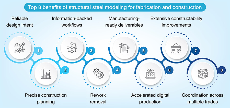
Adopting 3D structural steel modeling ensures that complex structural assemblies easily integrate with architectural and MEP systems in the design or preconstruction phase of construction projects.
When structural consulting firms create the right design to fabrication workflows, Revit converts engineering intent at LOD 300 to constructible families at LOD 400. This includes accurate bolt-hole patterns as well as gusset plate dimensions. It is also possible to define weld clearances in these assemblies.
Granular 3D structural modeling ensures that parametric geometry stays compatible with high tolerance values required as per rules for fabrication and installation.
Integrating structural steel models with scheduling tools like Navisworks enables stakeholders to simulate complex scenarios like crane logistics and erection sequences. When temporal installation of primary frames vs secondary bracing is visualized correctly, it improves site staging and removes spatial problems.
3D steel models serve as a single source of truth as they replace inaccurate 2D sections with a navigable digital space. When you leverage this clarity, it improves RFI resolution and multi-trade coordination. Your stakeholders are able to highlight geometric inconsistencies before site mobilization starts.
Stakeholders can easily export accurate geometry using IFC formats. When this synchronization happens, it can help quantity takeoff experts automate the material quantities. It also supports assembly marking, which erases manual layout issues and improves productivity.
Structural steel models replace ambiguous 2D drafting with precise 3D geometry. This data is fed directly into machines for manufacturers. Guesswork is completely eliminated in this workflow, and it also ensures all the connections are fabricated with precise geometry.
When your company relies on model-based takeoffs, it helps your team extract plate volumes, linear weights, and bolt counts. Metadata of this level helps with precise procurement and reduces scrap using improved nesting. You can also track material grades in real-time.
When data is directly fed into manufacturing equipment, it shortens the lead time. Applying automation within assembly marking and seamless shop drawings makes the manufacturing process simple. This increases the manufacturers’ throughput and eliminates rework during assembly.
Tired of steel fabrication rework caused by legacy tools?
Contact our team »If you employ automated 3D clash detection, it can erase spatial interferences between steel components and MEP equipment during preconstruction.
Navisworks is a powerful tool to identify clashes in a federated model. For example, if a structural member intersects with MEP ductwork or interferes with reinforcement or cast-in-place embeds.
Various teams working on the federated model need BIM coordination that is iterative and helps alter steel node topologies and MEP routing. Since these modifications and adjustments are made virtually, it ensures that precise fabrication data reflects the clash-free model.
Conflict resolution in the preconstruction stage removes site delays and rework. It ensures that all the RFIs and modifications are resolved before construction begins. Also, when there is a perfect fit between disciplines, it helps your firm reduce compounding costs related to welding, schedule halts, and re-drilling.
If Revit is utilized to build steel models, it develops documentation that is ready for fabrication. Shop drawings and other compatible data are taken from parametric 3D structural connections.
3D BIM structural models ensure generation of precise and detailed assembly drawings.
When parametric detailing is adopted, it thrashes out manual errors through digital bolt-hole spacing, plate alignments, and weld symbols.
If a centralized database is shared between steel fabricators and detailers, it eradicates data silos. Once the data is synchronized in real-time, it ensures that the material availability and shop floor capacities are mirrored in the final assembly.
Get construction-ready steel models that are built with AISC standards.
Contact Us Now »Revit 3D modeling ensures direct fabrication. It automates cutting and assembly based on high performance and parametric digital data.
Integrated 3D models automate the creation of NC files. It fuels robotic cutting and drilling lines with precision. This removes manual markers, which ensure complex geometries are machined as 3D modeled.
When your team uses interoperable formats like IFC4 or DSTV, it ensures there is no loss of data when it is migrated from design to fabrication. This connection makes procurement seamless and assembly programming effective.
If unique digital IDs are integrated in the model, it can help stakeholders facilitate real-time tracking from the mill to the worksite. Moreover, it improves material certification monitoring and refines weld inspections.
If you are an engineer or contractor, 3D steel modeling in Revit can help you enable improved coordination and spot spatial interferences. It can also support steel fabricators to refine fabrication processes and achieve the required deliverables.
When 3D structural steel models are used, they help firms simulate crane placements. It helps all stakeholders understand how equipment can be maneuvered safely in tight spaces. Visualization of this level avoids rework and delays on the site.
Accurate and LOD-based 3D models provide accurate dimensions that are required for fabrication in a controlled environment. When complex steel members are prefabricated, it ensures minimal material waste and speeds up timelines.
If your team has the capability to integrate site-driven data into the model, it ensures your structural design works with utility layouts and boundaries. Alignment at this precision reduces surprises and ensures higher constructability.
A study suggests that 35% – 45% of steel by mass of load bearing is not mandatory to achieve structural efficiency and optimization.
Source: sciencedirect.comFederated Revit models enable quick clash detection to ensure architectural and MEP systems fit well with structural steel.
Within a 3D model, aesthetic intent is understood well as spatial volumes and ceiling heights are well defined. When you are able to place columns and braces well, it avoids visual blocks and integrates well in the layout.
Preconstruction integration allows the right placement of web openings and beam penetrations for ductwork. Preemptive coordination reduces onsite drilling and ensures every mechanical component navigates swiftly in the structure without any conflicts.
When stakeholders in your project adopt a federated BIM environment, it makes real tracking of steel members swift. A seamless workflow enables updated geometry, error reduction, and cuts in late-stage modifications.
When an integrated BIM workflow is used, it optimizes the overall lifecycle – from design to fabrication and installation. It also helps your project team derive error-free shop drawings.
This is a crucial process that closes the gap between conceptual framing to automated fabrication, and erection sequences. If you can maintain information continuity, it can help you remove manual entry issues and uphold structural integrity.
Cloud-based tools help engineers, steel fabricators, and other stakeholders share RFI live 3D models and RFI updates. This clarity demolishes silos and facilitates a collaborative structure for technical data to flow within teams.
Continuous conflict detection and virtual walkthroughs help spot constructability problems before steel members can reach the worksite. Financial risks can be hugely reduced with this approach as we optimize change orders and can make sure installations don’t throw surprises.
Deeper digital integration will likely define the future of structural 3D steel modeling. Revit will be at the core, while APIs and Dynamo automation simplify complex connection logic using algorithmic accuracy. Navisworks will extend the benefits of structural steel modeling with precise clash detection and predictive erection sequences.
This synergy will help your firm eradicate numerous issues, to create a path where code-led structural 3D modeling converts into robotic fabrication and precise site execution.
We help you build structural steel 3D models with precise member sizing.
Get in touch with us »Bhavesh Umraniya is a BIM MEP expert with over 10 years of experience in the mechanical BIM field. Having, worked on multiple MEP projects worldwide, he is always looking for ways to enhance design quality and project productivity through technology interventions and process excellence. His exposure to various residential and commercial sectors, including hotels, airports etc. makes him a go-to authority in the BIM MEP space.
You may also like
Point Cloud to Revit: The Backbone of Scan to BIM Projects
The Role of Millwork Detailing in Modern Architecture