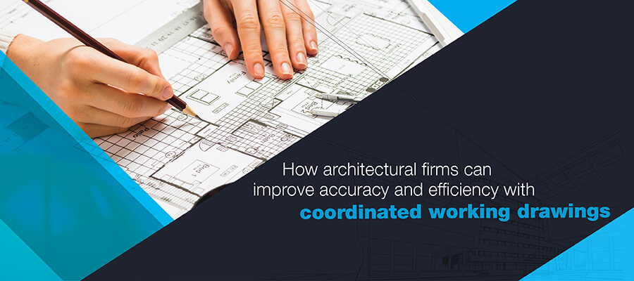
Coordinated working drawings are critical for obtaining construction permissions and providing accurate and detailed engineering information to contractors. Architects create these drawings to help contractors execute site projects without hassles, enhance construction site safety, and reduce project hiccups.
Design drawings, or coordinated working drawings made by architectural firms, are used in obtaining construction permissions and for executing onsite work. They contain all relevant construction phase details required by engineers and contractors to erect a project. They also act as a project validation logbook for authorities to verify periodic regulatory compliance. Acting as fieldwork manuals for construction project teams, they carry all important guidelines and details to be followed for construction safety, smooth project work and meeting of deadlines.
The same working drawings can, however, add to confusion on site if they lack coherence. This is why, coordination in preparing working drawings is critical at the pre-construction stage. Coordinated working drawings resolve conflicts and clashes beforehand, and thus serve as better field manuals for project teams.
In this blog, we discuss the issues that architectural firms solve with the use of coordinated working drawings, and the challenges faced in effecting such coordination using legacy methods.
Traditionally, working drawings were 2D orthogonal projections drafted according to desired scales. But they posed a series of challenges for architects and architectural firms such as:
Get 360 degree visualization for your projects with our architectural BIM services.
LEARN MORE HERE »Architectural firms extract detailed and information rich coordinated working drawings from 3D BIM models to get quick construction permissions and make the handover process to contractors easier and smoother. A few of the benefits of coordinated working drawings include time savings, simplified construction, early error rectification, change order avoidance, etc.
A dataset of coordinated architectural drawings in the preconstruction stage sets a strong foundation for onsite construction. A 3D model coordinated with various trades and architectural drawings pulled from a clash-free model reduces design changes in the preconstruction stage. Identifying, rectifying, and documenting design errors in the early stage, lessens construction ambiguities.
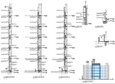
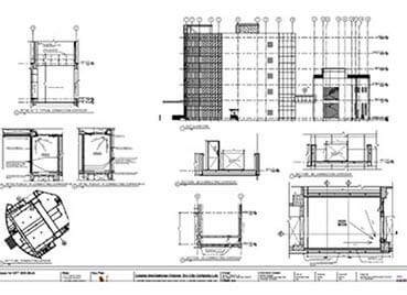
Coordinated architectural working drawings extracted from clash-free 3D BIM models are accurate and complete. Architects can leverage several parameters by pulling out precise coordinated data from 3D models that include the project name, contractor notes, room titles, etc. With checklist in hand, drawing readability is improved and architects and get a clear graphical representation or visualization of the project.
Reduce onsite errors and clashes with coordinated working drawings.
Read more here »Parametric 3D modeling in Revit® enables architects to easily update the information contained in the 3D model. Model-wide changes are automatically reflected in the 3D model while storing multiple revisions on a cloud-based platform. Architects use BIM services to access these detailed 3D models to extract accurate, coordinated, and clash-free working drawings, leading to fewer RFIs and change orders.
With every revision stored on a cloud-based platform, tracking updates or changes becomes quick and easy. Quick and proactive collaboration through digital platforms reduces the need or time to create and process RFIs. Significant reduction in RFI creation leads to greater cost savings and seamless construction.
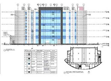
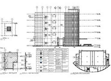
Working drawings obtained from Revit 3D models carry all information needed for greater transparency, quick client approvals and permissions. Detailed data on elevations, floor plans, foundation plans, roof framing, section views, etc. reduce rework and promote better construction through consistent industry standards.
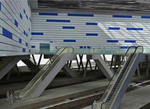
Coordinated drawings enable quick client approvals for a railyard project in Australia
 BIM Clash Detection
An architectural firm from Australia outsourced its architectural 3D visualization needs to Hitech CADD Services for a railyard project. With building construction plans shared as input, 3D visualization models enriched with coordinated working designs of the railyard were required. The team used Revit to build the deliverables which enabled:
Clash-free working drawings lower the risk of miscommunication and improve constructability. The 360-degree visualization of physical space represented in coordinated working drawings solves design coordination issues in the pre-construction stage. When design issues and clashes are resolved in the early stage, it leads to reduction in errors during the later stage of construction.
360-degree visualization with coordinated drawings ensure hassle-free construction
 BIM Clash Detection
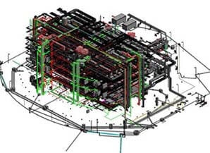
Hitech CADD Services were approached by an architectural firm from Gujarat, India to create a coordinated Revit 3D model combined with sheet setup for a commercial data centre building.
With 2D drawings provided as input, the team at Hitech CADD Services built a coordinated and clash-free 3D model. The 360-degree visualization with accurate construction documentation and complete sheet setup helped the client:
 Coordinated working drawings for a data centre building
The precision and efficiency of architectural working drawings can be improved with Revit automation using Dynamo. Visual programming tools like Dynamo help architects and designers speed up the modeling process and create multiple design prototypes.
Automation-centric Revit content promotes greater standardization enriched with design validation and plan compliance. Revit automation using Dynamo offers a host of benefits including automating repetitive tasks, better workflow automation, conflict resolution, specifications enrichment, parameter setting, etc. Extracting architectural working drawings from automated and validated 3D models ensures their accuracy and efficiency.
Gain 50% time savings and 100% accuracy with Revit automation using Dynamo for your project.
Read full case study here »Architectural working drawings not only help architects gain quick approvals by bringing greater project clarity via enhanced visualization, but also help architects communicate design intent better with other stakeholders. These detailed drawings help architectural firms deliver construction details to contractors so they can execute the onsite installation process as per the design specifications.
BIM automation has eased the creation of working drawings to a large extent. BIM-based coordinated working drawings will continue to remain crucial for architects and other stakeholders to achieve confident bids, quick approvals, and greater buildability.
You may also like
Top 5 Global MEP BIM Outsourcing Companies
Top 5 Architectural BIM Companies to Outsource
Top 5 Sheet Metal Design Companies to Outsource