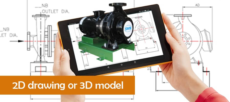
Metal fabricators need to make a choice when it comes to choosing the mode of planning and visualization of projects based on complexity – either using 2D drawings or 3D models. 2D is best suited for simple cutting and 3D modeling in sheet metal design for assemblies with complex parts. Fabricators are finding ways to combine these two to create what are known as hybrid workflows in order to produce better results.
Table of Contents
Metal fabrication has to be accurate to avoid delays in production, rework and materials wasted. Therefore, every design decision made at the planning stage impacts the entire fabrication process directly. 2D CAD drawings for metal fabrication are simple and can be produced quickly. They are suitable for simple layouts and flat patterns. However, 3D models are good for producing detailed views from various angles, which help to ensure that every part fits into the other without any alignment problems.
The workings in the metal fabrication industry are such that there has to be a balance between using 2D and 3D. Particularly where the new projects involve both cutting operations, and intricate assemblies. Furthermore, decisions like the choice of the appropriate sheet metal design software can be crucial based on whether the project involves CNC machining, laser cutting, or complex multi-material assemblies.
This article is aimed at helping metal fabricators to arrive at an informed decision in the choice of 2D vs 3D modeling for metal fabrication, so that both efficiency and accuracy can be maintained throughout the production process.
| Point | Description |
|---|---|
| Visualization | 3D CAD improves design visualization in fabrication. |
| Precision | 3D models provide exact measurements, minimizes errors. |
| Collaboration | 3D formats improve teamwork among all stakeholders. |
| Simulation | 3D CAD allows virtual simulation to spot design flaws before they occur. |
| Efficiency | 2D is fast for simple jobs; 3D makes complicated projects simpler. |
A 2D CAD drawing represents a part or assembly in a 2D plane, typically used for simple cutting operations and schematics. The 2D drawing includes measurements, specifications and annotations that specifically tell fabricator how to build a specific metal component.
These type of fabrication drawings form the basis for getting the flat pattern design and eventually the manufacturing right.
There are many tools available to create 2D CAD drawings such as AutoCAD for sheet metal work, Inventor and SolidWorks. Once a 2D drawing is created it may be saved/exported into file formats such as DXF or DWG. These formats give you CNC-ready files.
Applications:
A 3D CAD model is a complete digital model of a product that can be viewed from any angle. A 3D CAD model shows height, width and depth whereas a 2D CAD model only shows height and width. A 3D CAD model is particularly useful when creating complex geometries. To create a 3D CAD model you can generally use SolidWorks, Inventor 3D Modeling and Fusion 360.
Using these tools you create 3D CAD files that allow metal fabricators to visualize and manage complex assemblies and verify that each part fits properly.
Also 3D CAD modeling for sheet metal fabrication allows the engineer to input material properties including thickness, weight and tensile strength in the model, which are important factors for metal component detailing.
Applications:
Whether to opt for 2D drawings or 3D Models depend on the specific demands of your project. Understanding the difference between 2D and 3D CAD is very important in this context. 2D drawings are preferable when working with cutting paths and simple parts; they are faster to develop and immediately compatible with CNC equipment.
Complex products requiring multiple parts are ideally represented by 3D CAD models. In addition to being able to represent part details in detail, 3D CAD models enable you to track material properties and create exploded views to aid in product assembly. Having all aspects of your product in one model gives you an overall representation, therefore minimizing potential for confusion that may occur with multi-piece assemblies or those with complex geometry. 3D CAD models however have the disadvantage of expensive software and/or extensive training.
Therefore, many metal fabricators take advantage of a hybrid system that includes 2D CAD drafting for metal components for general operation and 3D models for assembly confirmation. Using this method will allow you to accomplish your goals while ensuring both speed and precision and minimize the number of errors when you are aiming for production workflow optimization.
Convert legacy paper drawings to accurate CAD files for quick reuse.
Get in touch with us »| Point | Description |
|---|---|
| Clarity | 3D models provide clear visualization, reduces misinterpretations. |
| Accuracy | Accurate measurements, minimizes issues with manufacturing accuracy and tolerances. |
| Workflow | Using these streamline collaboration and communication among teams. |
| Flexibility | Being flexible 3D allows for easy modifications, adapting to design changes quickly. |
| Cost-Effectiveness | 3D reduces rework and material waste. |
Pros:
Cons:
Pros:
Cons:
2D CAD drawings are very good when needed quickly by the fabricator for laser cutting, water jet cutting or sheet metal forming. These are very easy to use for weldment plans, brackets, and electrical layouts which do not require visualization of the “depth” of an item.
3D CAD drawings are ideal for large assemblies of multiple components such as metal stairways, railings or frames used in the construction industry, as they allow the fabricator to evaluate different materials and visualize how each component relates to other parts of the assembly. 3D CAD drawings can also be used for sheet metal bending simulation.
One of the biggest advantages of 3D CAD drawings is to enable the fabricator to see the potential problem areas at an early stage, such as misalignment or clearance, prior to production. For projects using digital twins (virtual models used for monitoring and maintenance purposes), three dimensional CAD drawings are important as they simplify tracking and controlling versions over time.
Choosing the right format – 2D or 3D for each task within a metal fabrication design workflow will give you better results and less rework.
Scale variations instantly with configurable 3D sheet metal designs.
Contact us now »3D CAD modeling created 1,500+ drawings/month
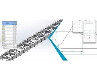
A manufacturer in Russia that produces large-sized steel structures experienced difficulty extracting design intent from their 2D PDF drawings and they could not meet the extremely tight delivery schedules. They did not have sufficient resources to produce quality CAD deliverables and required better, quicker and more precise turnaround times.
Hitech CADD Services converted 2D PDF drawings and Bills of Materials (BOMS) and created fully developed 3D SolidWorks models and detailed drawing of all parts in the assembly, handled part name nomenclature questions and provided peer QC, producing approximately 1500 drawings per structure and verified assemblies ready for fabrication.
The final deliverables included:
 Assembly Drawing in SolidWorks
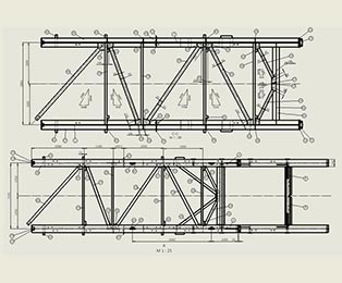 Part Drawing in DriveWorks
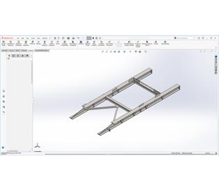 SolidWorks 3D Model of Steel Structure
 Estimation Sheet & 3D Model
2D CAD drawings have their advantages when creating cutting paths and flat layouts for laser and waterjet cutting; while the benefits of 3D CAD modeling for sheet metal product fabrication ensure correct fit in complex assemblies and provide clarity for communicating among teams working with complex designs. Using both formats will allow fabricators to complete project specific requirements quickly and efficiently by making use of CAD.
Combining these formats will enable teams to improve their efficiency by minimizing lead times, reducing production errors and revisions. Additionally, following fabrication drawing standards will ensure that each design is optimized for fabrication and takes into consideration limitations of materials used as well as capabilities of the machines.
CAD cloud platforms allow stakeholders to collaborate more easily, so everyone will have access to the most up-to-date designs whether they be 2D or 3D. Additionally, using ASME Y14.5 standards will ensure accuracy for dimensions and tolerances in both drawing types, minimizing miscommunication and enhancing workflow.
Using this dual format will provide fabricators with the ability to take on a wide variety of projects, including simple profiles to complex assemblies.
The hybrid 2D/3D CAD workflow is a major game changer for the sheet metal fabrication industry, by allowing users to take advantage of the capabilities of each format to produce the best possible result. The 3D model serves as the core model used for all design work prior to actual production, including the development of initial conceptual designs and a comprehensive Design for Manufacturing (DFM) evaluation prior to production.
At the base of this efficiency is ensuring a seamless 2D to 3D CAD conversion process. While you are developing your design using 3D modeling techniques, the software will do an excellent job of automatically creating the required 2D geometry (the flat pattern), which is immediately available to you. The 2D data is then exported to DXF/DWG file types, the type of files that CNC nesting software requires to utilize the maximum amount of material and minimize scrap material.
Since there is a direct relationship between the 2D and 3D files, when any modifications occur within the 3D environment, the updated 2D files ready for production are modified in real time, eliminating the potential for errors occurring while converting from 3D to 2D. With the integration of this digital thread, users can eliminate long lead times, reduce the requirement for manual rework, and ultimately deliver a high-quality product at a reduced cost.
Following DFMA guidelines for sheet metal products shave off 56% of the TAT
US based fabricator of sheet metal building products and electrical enclosure was experiencing extreme workloads, irregular customer demand and a multitude of errors due to use of PDF’s and sketches. The need for skilled designers to rapidly develop 3D models, assembly drawings and 2D fabrication drawings was at an all-time high.
Hitech CADD Services converted the fabricator’s PDF drawing and sketch documentation into SolidWorks 3D models and 2D drawings utilizing top-down parametric methodology along with DFMA guidelines. Hitech CADD also maintained a work log to insure quality control and coordinated a prioritized team workflow to provide timely delivery of the manufacturing ready documentation.
The results were:
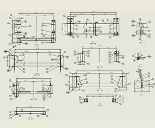
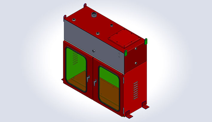 Enclosure with Tank
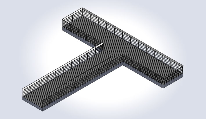 Pier Railing for Park
Selecting the correct CAD format (2D drawing or 3D model) will make an enormous impact in how smoothly your fabrication process will flow. 2D drawings provide a quick and cost effective solution for CNC programming and for those projects where you require a fast turnaround. However, 3D models are ideal for complicated assemblies requiring a deeper level of detail and precision.
Using a hybrid approach will allow you to receive both the benefits of 3D modeling for fabricators and the rapid production lead times available with 2D drawings. In addition to selecting the correct CAD format, implementing DFM (Design For Manufacturing) principles and utilizing online collaboration tools will also aid in streamlining your workflow while reducing the potential for costly errors and improving your overall performance.
Yes because 2D CAD file formats such as DXF files or DWG files are more than adequate for CNC programming purposes, especially in the case of laser cutting, plasma cutting or bending profiles.
The cost varies in accordance with the 3D CAD software used, the licensing fee chargeable and the training needed to bring users up to speed. Software such as SolidWorks and Inventor can be extremely expensive initially, but can be beneficial when used correctly over the long term.
When using Design For Manufacturability (DFM) you are effectively designing a product to be manufactured as efficiently as possible, thus producing less waste, lower costs and fewer mistakes.
Definitely yes, as 3D CAD can make a considerable difference when it comes to prototype & parts assembly. It helps to eliminate all types of mistakes and design changes which can take weeks off lead times.
The simple answer is use cloud based platforms. This allows everyone access to the very latest CAD files and also gives far greater control over different revisions of the design, which is extremely important to eliminate mistakes through the use of out-of-date files or changing files unforeseeably.
Broadly speaking, 2D CAD tools are much cheaper, and 3D CAD tools are much more expensive due to their features and higher specifications in systems required to run them.
With the use of 3D CAD models you get a much better and more efficient BOM (Bill of Materials) generation for fabrication as this will track automatically all the various components and their quantities through an automatic calculation. This leads to expedient materials procurement and also easier production planning.
With sheet metal CAD design you need software which properly accommodates the various factors of bending, folding and flattening metal, with the specific properties of the material and methods involved in manufacture.
Usha B. Trivedi is an engineer and she contributes in-depth articles for mechanical and industrial equipment designs, furniture designs and fabrication sector. Her contributions are primarily focused on enabling engineering professionals, furniture manufacturers and fabricators to optimize design outcomes through CAD and CAE tools.
You may also like
BIM-Based MEP Coordination for Multi-Trade Collaboration