Building drawings are the most crucial deliverables created by architects and building engineers. These drawings provide general contractors, subcontractors, and owners with detailed instructions on executing a construction project. Each building drawing serves a specific purpose, whether it is conveying technical data, ensuring project benchmarking, or facilitating compliance and approvals
Construction drawings contain accurate and detailed building measurements and provide clarity on various sections. A well-structured construction plan ensures that these drawings communicate ideas, anticipate problems, and define a building’s structural layout and its components. As a result, building drawings offer a complete visualization of how each building asset will function during construction.
There are different types of building drawings, including section drawings, elevation drawings, line drawings, sketches, development drawings, foundation footing detail drawings, and more. Each type of building drawing is created to communicate specific design intents and instructions for execution. Understanding various types commonly used by architects and building designers is essential for maintaining compliance with construction drawings standards.
In this article, we provide a list of 42 common types of building drawings along with their intended purposes.
Table of Content
Construction drawings convey detailed information essential for the building construction process, facilitating effective communication among architects, contractors, engineers, and other project stakeholders. Construction drawings serve various purposes, including:
Various types of design & construction site drawings convey essential design and construction information for a building project. These building construction drawings can be categorized into the following sets:
Architectural drawings provide a technical representation of building drawings before construction begins. They are created with lines and projections and are drawn to an accurate scale. Common types of building design drawings that fall under architectural drawings include:
Concept drawings are preliminary building sketches, either hand-drawn or digital, that provide an overview of a building for clients. Though not detailed, they visually communicate architectural ideas, capturing the essence of the design through quick ideation and iterations.
Site plans are based on bird’s-eye views of a construction site including the primary and auxiliary structures. Site plans, as part of construction drawings, are used for understanding the project scope, building enhancements, and topography that include pavements, roads, etc. It also shows neighborhood surroundings and site accessibilities.
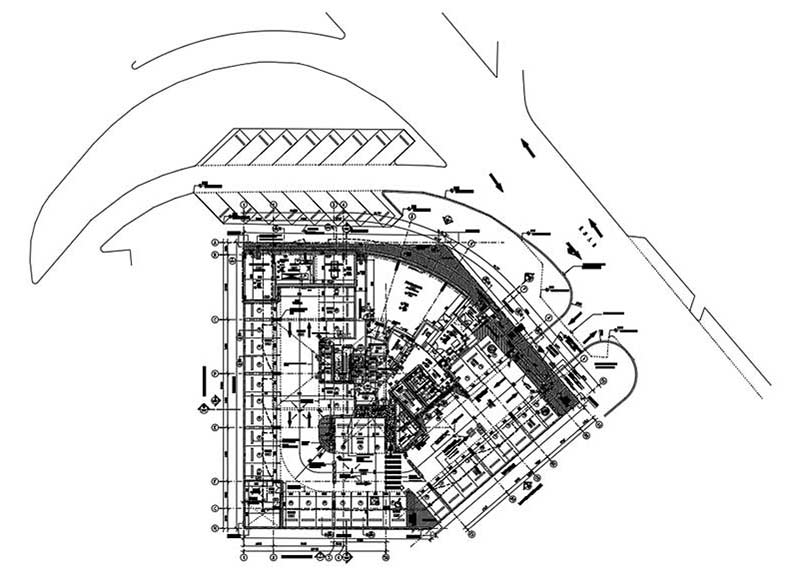 Site Plan Drawing
Floor plans illustrate detailed room layouts, dimensions, and installations for house plans, shops, and commercial projects. They help in understanding dimensions, spatial use, and installments during construction.
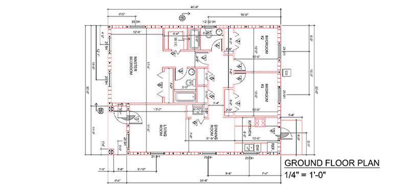 Ground Floor Plan
Cross-sectional drawings help architects visualize the layout of architectural components from a vertical perspective. They help architects get a snapshot of both visible and concealed assets. They are key deliverables in visualizing both sides of a wall.
 Sectional View/Drawing
Elevation drawings represent the length, height, width, and appearance of a building. They help architects and building engineers in understanding the direction of the wind and sun associated with the building.
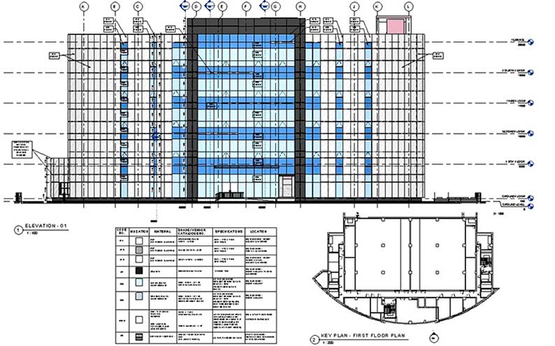 Elevation drawings
Landscape drawings represent the aerial view of a building with assets including lights, pools, trees, levels and external assets such as parking areas, roads, pavements, etc.
Finishing drawings include floor patterns, type of floor, paint color, false ceiling, and its shape. These Finishing drawings have a close relationship with elevation drawings and 3D building drawings, as they focus on finer architectural details. They illustrate the aesthetic value of the building and also include other finer details of the building.
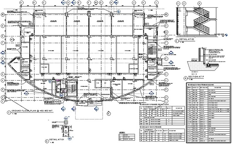
Working drawings support contractors in getting details and information on various components for better project execution and to help fabricators manufacture components based on the overall design. However, coordinated working drawings play a crucial role in eliminating clashes, enhancing design precision, and improving construction documentation.
 Working Drawings
General notes are annotations or instructions to provide specifications and additional information related to the construction drawings. These convey guidelines and details to showcase the graphical elements. General notes add clarity to drawing aspects like tolerances, dimensions, etc. General notes also include codes and standards, assembly guidelines, design intent, and revision history.
As-Built drawings are essential construction documents that illustrate the differences between the original plan and the final built construction. Contractors may need to make changes to the original design or construction based on various circumstances. These As-Built plans are built during construction or after completion.
Single-line drawings illustrate the room structure with lines drawn as different room configurations. Single-line drawings mark room sizes along with accurate labeling. They are representation drawings used to visually illustrate the preliminary design idea related to architectural, mechanical, and electrical systems etc.
 Single-line Drawings
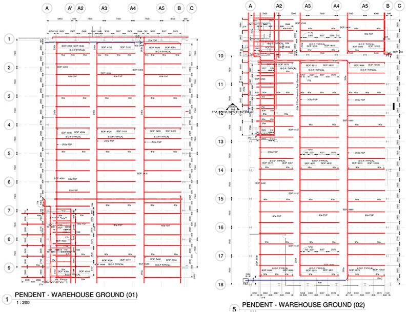
These drawings are made for structural and MEPF systems. Penetration drawings illustrate shaft penetration, sleeve locations, and walls. They also include rough-in dimensions and the size of the opening.
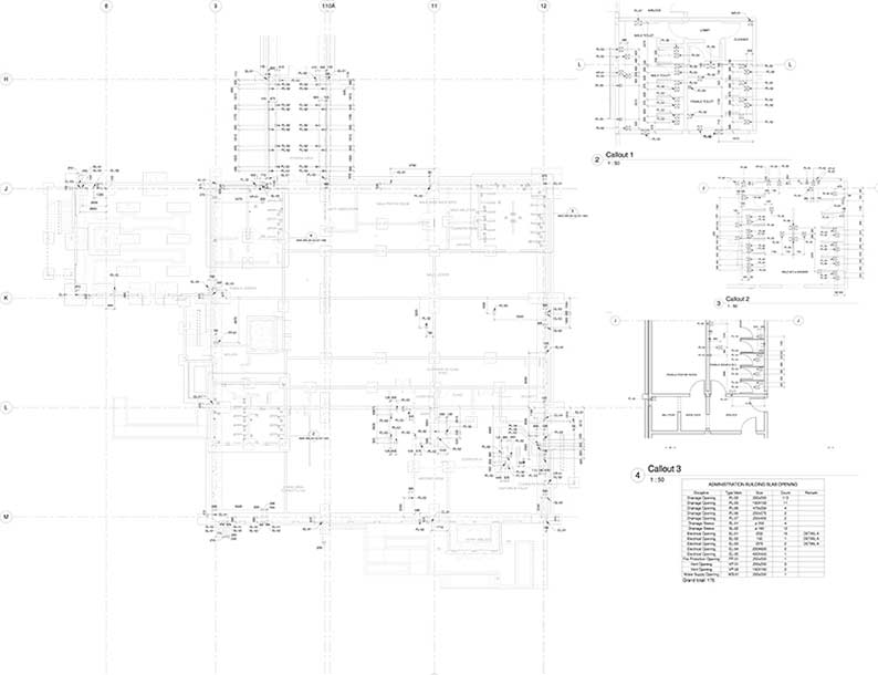 Penetration Drawings
Shop drawings are used by contractors and sub-contractors or by manufacturers and fabricators to understand how an asset needs to be manufactured and installed. These drawings ensure conformity with the original design and asset specifications.
 Shop Drawings
Discover the key differences between shop, construction, and as-built drawings
Explore our Article Now »Location drawings show the demarcation of the site with respect to connectivity of local bus stop, airport, metro station, parks, schools, gas stations etc.
GA drawings are created at every stage of design and development. These drawings show the dimensions and relationships between various elements. These drawings may also include specifications and detailed drawings. Details about other elements include symbols, notation, title blocks, etc. The drawing scale reflects the level of detail, and GA drawings can be prepared through CAD-based tools, hand-drawn sketches, or 3D BIM modeling.
Structural drawings, also called engineering drawings focus on the structural side of the project. Included in the proposal documents, these structural drawings serve as a guide for the workforce.
Centerline plan shows the X and Y dimensions of all structural elements like foundation, column etc. with reference to the datum level (00). It shows the context of the building outline with respect to its outer boundaries and roads.
Excavation drawings provide details about the dimensions of the building excavation, along with excavation extent, soil removal, and the excavation sequence. Excavation plans outline strategies for site preparation, safety measures, depth measurement, excavation, and equipment use.
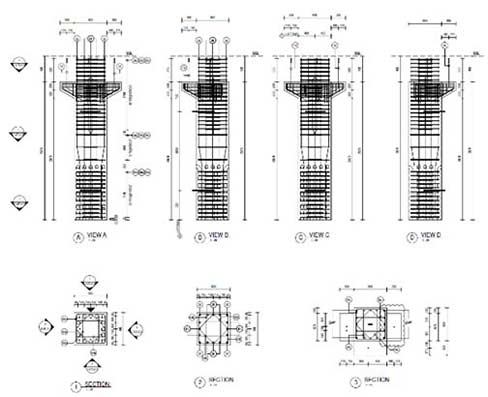
Column drawings showcase the column structure, column size, column height as well as the accurate distance between building columns. It supports building teams to organize and deliver information through clean and structured representations.
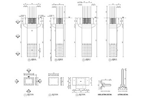 Column Drawings
Wall section drawings show all building components from foundation to roof. One can easily get respective levels, size and location. Example- we can get an idea of plinth-beam, lintel beam layout, and roof beam along with details such as its size, level and position.
The roof layout exhibits detailed roof faces, floors, and other surfaces with precise edge data. It gives a clear idea of levels of the roof, parapet location, slope for water drainage and respective outlets and location of overhead water tank. A roof layout ensures the durability and security of the roof structure.
A block plan represented in scales includes neighboring buildings with boundaries, roads, and other assets. These plans show visual representation of blocks within cities for town planning. They serve as references for construction and organizing the building process. Block Plans help architects, builders, and engineers coordinate better for accurate project execution.
Framing plans are similar to beam layouts including frame size and position. These can be used for concrete, wood as well as steel material planning. These drawings outline the arrangement, location, and size of structural components including beams, columns, and walls. Framing Plans provide necessary information to indicate the stability and integrity of the overall building.
Component drawings are given by the product manufacturer with detailed information on marking and sub-parts. These drawings include views from various angles including top, front, and side with accurate annotations and measurements. They are used for manufacturing, assembly, and maintenance along with intricate details of every component.
Fabrication drawings provide detailed information regarding assembly and fabrication of various MEP components as well as structural elements. They supports engineers and contractors to collaborate and get the required results for a construction project. Fabrication drawings support communication, coordination, and implementation of building projects.
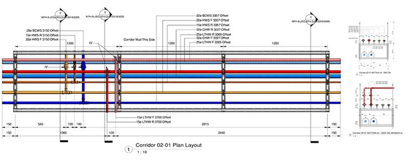 Fabrication Drawings
Assembly drawings exhibit the connection between two structural assets. It includes sectional and elevation views. They illustrate technical details, arrangements, and relationships between complex systems. Assembly drawings play an important role in the production and integration of multiple components.
Similar to concept drawings, these drawings transmit rough ideas to design teams. Design drawings communicate design intent and building specifications. They also provide information on layout, materials, dimensions, and project systems. Design drawings include sections, elevations, and MEP drawings to realize accurate coordination and construction.
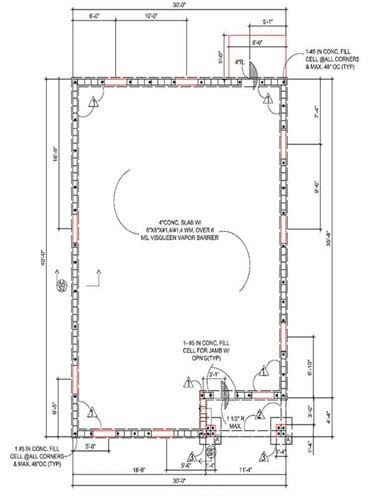
Foundation plans are created for any building floor that conveys size, dimensions, shape, levels and other floor configurations. They also indicate the position and location of beams, footings, and various structural elements to ensure stability, durability, and load-bearing capacity.
Mould drawings provide details to manufacturers regarding prototypes of products/ columns including the concrete casting with size and dimensions, in a plan using a mould. This helps manufacturers speed up the production of concrete elements and also the onsite workers easily assemble the mould as per instructions on the drawing.
Erection drawings provide an idea of the site erection for precast structural elements. The unique ID of each structural element is also mentioned in erection drawings along with respective erection sequence, which helps in faster and error-free onsite construction.
Installation drawings support contractors with visualization of the installation of HVAC systems. They serve as visual guides to pinpoint the location of MEP systems with interconnections. Installation drawings reduce errors, lower misinterpretations, and ensure streamlined implementation.
 Installation Drawings
An electrical drawing shows electrical outlets, connections, switches, lights, fans, and other fixtures. These drawings also illustrate load capacity, and data on heating and AC systems. Electrical drawings are visual representations of electrical systems with components and relations. Lines, symbols, and labels are used to depict functions and connections.
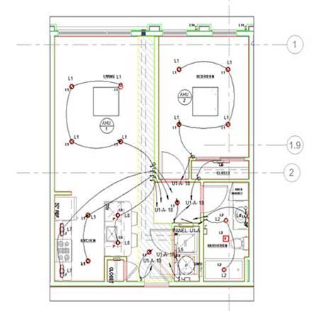 Electric Lighting Plan
Plumbing drawings include the location and marking of the plumbing assets. That includes water pipes, drainage systems, sanitary systems, and other plumbing components. These drawings also mark the location of water outlets and taps.
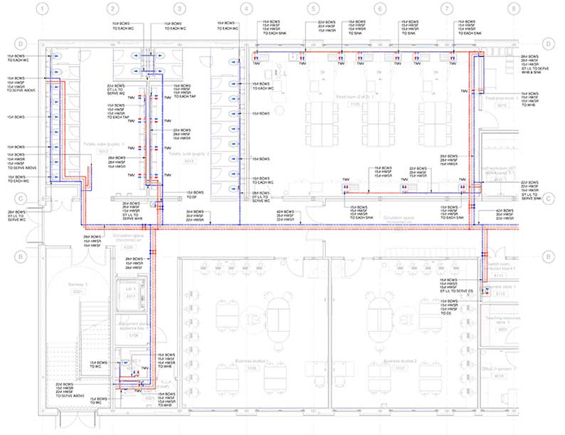 Plumbing Drawings
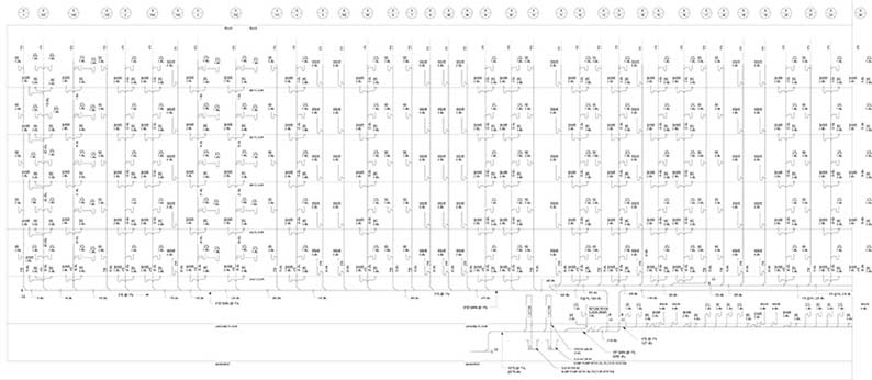
Drainage drawings include diagrams that represent the flow of water into and out of the building. They also include various pumps, water tanks, vents, drains, etc. They depict the layout of drains and pipes with size, direction, and flow of waste and water.
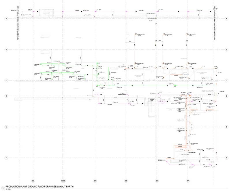 Drainage Drawings
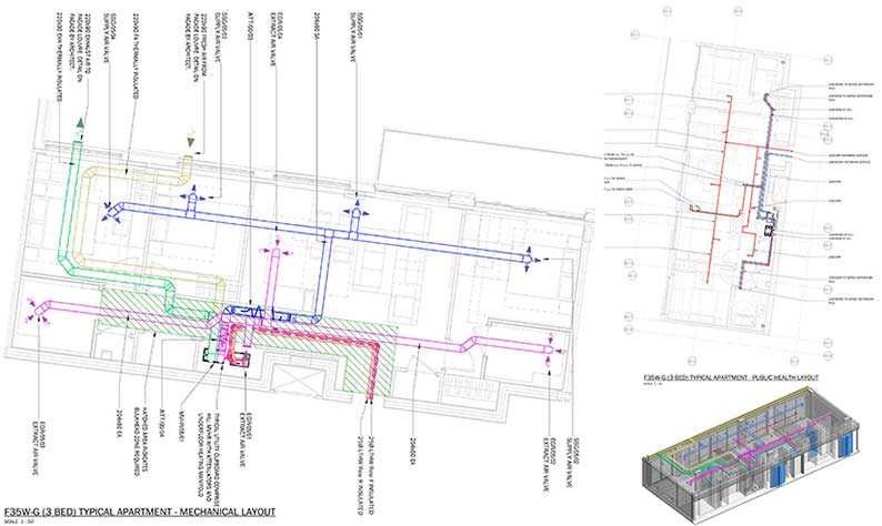
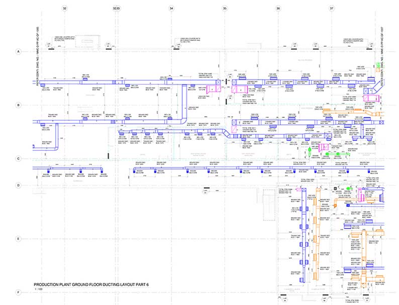
Known as mechanical drawings, these drawings provide data on HVAC systems including AC systems and their layout. They serve as a blueprint for HVAC systems including the layout, specifications, and components required for accurate installation. Illustrating placement, ductwork, and controls ensures efficient design and construction of HVAC systems.
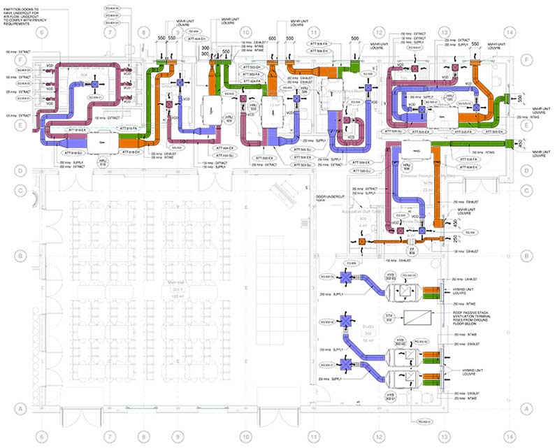 HVAC Drawings
These drawings are created before construction begins. These include the position of fire hoses, water outlets, and other fire protection assets. They ensure the safety of buildings and occupants. They outline elements to locate sprinkler systems, fire alarms, fire extinguishers, and fire exits. A clear understanding reduces risks, improves fire safety planning, and reduces potential disasters.
 Fire Protection Drawings
Detail drawings include the geometric structure of the building including detailed designs. They provide accurate information on design, materials, dimensions, and instructions on assembly to minimize errors and ensure quality in fabrication and construction. Dimensions, materials, and features with symbols and annotations improve accuracy and clarity for architects, technicians, and engineers. Detail drawings ensure quality standards throughout manufacturing and assembly.
 Detail Drawings
Perspective drawings are realistic drawings for an under-construction building that includes the spatial features of a building with 3D volumes. They add depth and object realism in 3D space based on a 2D surface. They ensure greater engagement and immersive representation through converging lines and vanishing points.
These drawings serve as a guide for field personnel with data that includes materials, dimensions, assembly, etc. Production drawings communicate detailed data and specifications for manufacturing accuracy and uniformity. Consistent manufacturing of building components can be ensured with the use of production drawings.
These drawings are prepared about by-laws and implemented by an authority for approvals. These include detailed drawings, elevation drawings, and index plans. They provide a detailed representation of architectural designs for quick and accurate project implementation. They also include floor plans, sections, and technical details. Submission drawings drive faster permits, approvals, and successful execution.
Environmental plans demonstrate insights into soil sedimentation, erosion, plant removal, and chemical disposal procedures. Environmental plans are used to reduce the impact of construction on the environment. These plans include waste management, lower pollution, and the protection of natural resources. They also emphasize improved site management for erosion and biodiversity.
Presentation drawings are made for proposals, exhibitions, and publications and include a myriad of drawings. These drawings are crucial in design and architecture for an aesthetic visual representation. These drawings include elevations, perspectives, spatial needs, and materials. Textures, colors, and shades within presentation drawings improve the final deliverables with informed-decision making.
Survey drawings exhibit buildings or land that needs to be measured. These drawings deliver an accurate representation of the area under survey. They serve as valuable tools through measurements, features, and landmarks with details like levels and slopes for surrounding sites and topography.
This article has explored 42 types of construction drawings commonly used in building design. From architectural plans and elevations to structural and electrical drawings, each type plays a crucial role in communicating design intent and guiding construction processes. Architects, engineers, and stakeholders are increasingly collaborating with reliable BIM service providers for architectural drafting services to ensure successful project outcomes.
Whether it is conveying spatial relationships, illustrating material choices, or outlining technical specifications, Hitech CADD Services offers a wide range of architectural drawing and drafting services customized as per your project needs. By harnessing the power of visual representation, our drawings lay the foundation for the realization of innovative, functional, and aesthetically pleasing structures. As industry continues to evolve, this blog serves as a valuable reference, fostering knowledge, creativity, and excellence in the world of building design.
A building design drawing refers to a visual representation of the architectural and structural elements of a building or structure. It is a detailed graphical depiction that communicates the design intent and specifications to various stakeholders involved in the construction process. Building design drawings play a crucial role in translating the architect’s vision into a tangible form that can be understood and executed by engineers, contractors, and other professionals.
Building design drawings encompass a range of drawings that collectively convey comprehensive design and construction information. Some common types of building design drawings include:
The 7 types of architecture include the following:
The different types of drawings used in construction include the following:
The various types of drawings in a set of construction drawings include:
Kaushik Gajjar is a licensed architect working as a BIM manager at Hitech CADD Services. With a work experience of over 10 years, Kaushik has successfully delivered various architectural projects to clients globally. As a “Best Young Architect” awardee, his creative architectural designing, planning, and knowledge of BIM tools and techniques ensure optimum client satisfaction.
Harika Singh is an academician and published writer. Her passion for engineering and technology reflects in the in-depth coverage she provides on technology trends. 20 years of work association with institutes of repute across India and the US positions her to provide valuable insights to business stakeholders on achieving scalability and operational efficiencies through digitalization.
You may also like
Point Cloud to Revit: The Backbone of Scan to BIM Projects
The Role of Millwork Detailing in Modern Architecture